
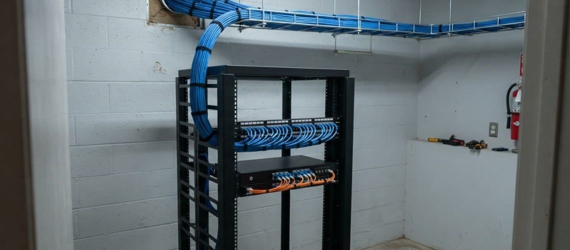
The cable choice is only part of a reliable network plan. A structured cabling installation in Dyersville should match copper or fiber to the connection’s needs and account for building conditions, pathways, and future growth. Category 5e copper cabling has a maximum distance limit of 90 meters, while fiber offers greater bandwidth and is immune to electromagnetic and radio-frequency interference.
Cable type matters, but the route through the building matters just as much. Existing pathways, construction details, and network-equipment locations all shape how a structured cabling installation is planned and completed.
This guide explains how to compare copper and fiber, assess building infrastructure, and plan cable routes for a dependable system. It also covers project decisions that affect installation, helping you understand what your Dyersville building may need.
Key Takeaways
- Match cable choices to the connections each area needs, including backbone links and device locations.
- Plan the network layout around current operations and anticipated growth, rather than treating each cable run as a separate decision.
- Account for whether the project involves new construction or an existing building, since access and installation conditions shape the work.
- Review existing pathways and ceiling conditions early to plan practical routes and avoid unnecessary changes during installation.
- Coordinate cabling with network equipment and business systems so the finished infrastructure supports day-to-day operations.
Copper and fiber cabling
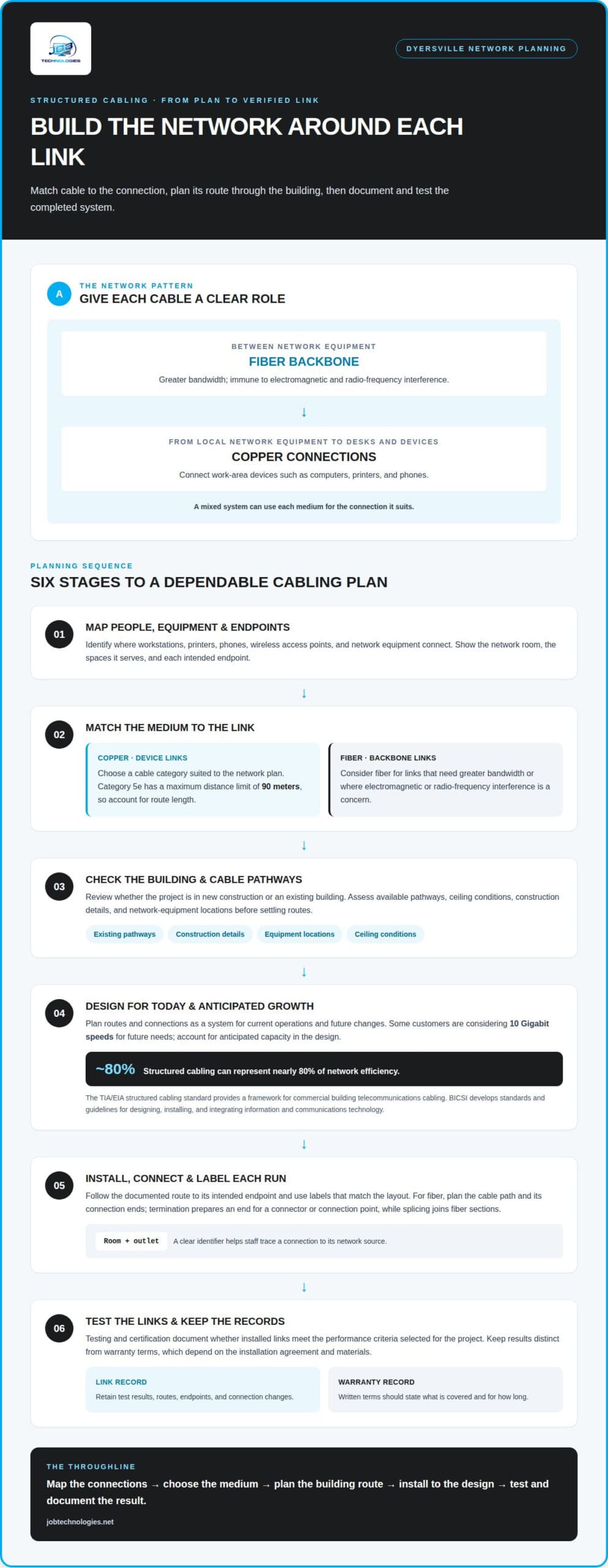
Choosing between copper and fiber starts with the connections each route must support. Category 5e copper cabling has a maximum distance limit of 90 meters, while fiber optic cabling suits links that need greater bandwidth. In Dyersville buildings, a network plan can use both rather than treating them as competing choices.
Copper data cabling connects devices such as computers, printers, and phones to network equipment. It can serve work areas where Ethernet connections are needed, with the cable category selected to suit the network plan. Category 5e has a defined distance limit, so route length matters when planning a connection from a network room to a device.
Fiber-optic cables carry data using light and are immune to electromagnetic interference (EMI) and radio-frequency interference (RFI). This makes fiber useful where those types of interference are a concern. Fiber also offers greater bandwidth than standard copper wiring, which is why it is commonly used for backbone connections between network equipment.
A mixed cabling system can give each medium a distinct role. For example, fiber can connect network equipment across a building, while copper connects local network equipment to desks. This separates backbone connections from device connections and lets the design reflect how people and equipment use each area.
Fiber-optic installation involves planning the route, placing the cable, and preparing its ends for connection. Termination prepares a cable end for a connector or another connection point. Splicing joins fiber sections, which can help create a continuous link between cable segments. The installation plan needs to account for these connections as well as the cable path.
Testing and certification document whether installed links meet the performance criteria selected for the project. Warranty options depend on the installation agreement and materials, so written terms should specify what is covered and for how long. Keep test results for the completed link distinct from the terms of its warranty.
Data cabling includes the cable itself and the connection components needed to bring each run into service. A design, for instance, may pair copper cable and termination points for office devices with fiber cable and connection hardware for a backbone. Selecting compatible components as one system helps avoid treating each cable run as a separate purchase.
For a structured cabling installation in Dyersville, start by mapping which equipment needs copper connections and where a fiber backbone makes sense. Then consider route length, potential interference, and how each end of a fiber run will connect. This gives each cable a clear purpose before installation begins.
IT staff often consider fiber-optic cabling for its quality and reliability. When selecting components, weigh those qualities alongside each connection’s purpose and route requirements. Tying cable choices to the role of each link helps staff assess the entire network design rather than treating cable selection as an isolated decision.
Structured cabling design and installation
A structured cabling design maps how voice and data connections serve each space, from work areas to network rooms. DIY installation can lead to poorly planned routes, inconsistent labels, and connections that are difficult to diagnose later.
Cabling System Design
Start the design with the building’s users, equipment, and communication needs. A network plan should show where workstations, printers, phones, wireless access points, and network equipment connect. For example, a floor plan can identify a network room and the work areas it serves, clarifying each cable route and endpoint.
The TIA/EIA structured cabling standard addresses commercial building cabling for telecommunications products and services. It provides a framework for designing a structured cabling system instead of treating every connection as a separate installation. BICSI’s International Standards Program develops standards and guidelines for designing, installing, and integrating information and communications technology.
Good network cabling design also considers how the network may change. Some customers are considering 10 Gigabit speeds for future needs, so the design can account for anticipated capacity rather than only current devices. Structured cabling can represent nearly 80% of network efficiency, making the planned routes, endpoints, and connections consequential to overall network performance.
In an office, the design may connect desks and shared devices to a central network area. In a data center, it must also account for equipment connections and how those links are organized. In both settings, the design should clarify how voice and data travel through the structured cabling system and where each connection terminates.
Installation and Administration
Installation turns the documented design into physical network cabling. Each run follows its planned route, reaches its intended endpoint, and receives a label that matches the layout. A clear label, such as a room and outlet identifier, helps staff trace a connection from a device back to its network source.
Administration continues after installation. Keep records of cable routes, endpoints, and connection changes so staff can understand the system when equipment moves or a workspace changes. For example, relocating a printer is easier when its former port and the relevant network-room connection are documented rather than left to memory.
DIY work can cause problems if the installed route differs from the plan or labels do not identify both ends. These gaps slow troubleshooting and complicate future changes. A managed installation keeps the plan, physical work, and records aligned, which is especially useful across multiple work areas or when the system supports both voice and data.
For a Dyersville project, network cabling planning can help translate business needs into a documented installation and an organized system for future administration.
Installation costs can also affect whether a business handles cabling in-house. A clear scope helps teams weigh the work against the need for documented routes, consistent labels, and maintainable connections. Planning before work starts can prevent each run from being treated as a separate task and keep the completed system aligned with the intended layout.
Building type and installation environment
A cabling plan should reflect the building’s layout, use, and construction stage. An office renovation, warehouse, and multi-building campus each bring different routing and coordination needs.
Multi-Building Campus Deployments
A campus deployment connects separate buildings while accounting for each site’s network needs. Start with a site plan showing equipment locations, work areas, and the links needed between buildings. For example, an office and nearby warehouse may need separate internal cabling plans coordinated to support communication between their networks.
Next, map how employees use each space and which applications need network access. A warehouse may need connections for shared workstations, while offices may support voice, data, and meeting-room equipment. Include the route between buildings in the overall design rather than treating it as a separate cable run.
Phasing can help coordinate campus work with active operations. The deployment plan can group work by building, identify areas that need access during installation, and document which connections will be brought online. This helps employees understand where work is taking place and keeps the cabling work aligned with business communications.
Building Services Cabling
Building services cabling supports systems that rely on communications wiring beyond individual desk connections. During planning, identify each application and the location of its equipment. For example, a shared conference room may need network access for communications equipment, while reception may need a connection for a phone system.
Coordinate the connection plan with the building layout. A floor plan showing equipment locations, work areas, and proposed cable routes helps the installation team understand how building services relate to network infrastructure. Distinguish business network connections from other building systems so each application has a defined purpose and endpoint.
Changes in how a building is used matter, too. Converting an office into a training room can change where employees need communications access. Recording intended uses during design helps determine where wiring should terminate and which areas need network connections, reducing the need for unplanned runs after installation begins.
Local Codes and Permits
For low-voltage cabling in Dyersville, code and permit requirements depend on the project scope and building conditions. Identify applicable local requirements before installation, especially for renovations or changes to building pathways.
Coordinate the cabling plan with the building schedule and the people responsible for the premises. For example, existing ceilings or shared pathways in a renovation may affect access to work areas. Documenting routes and work locations clarifies the project scope and helps coordinate cabling with other construction tasks.
For a campus or single-building project, keep installation records aligned with the approved scope and completed work. Clear documentation of cable routes and connection points gives facilities and IT teams a practical reference when applications move or spaces change.
Pathways and building infrastructure
Existing pathways determine where cables can run and how the network can expand. Before installation, map available routes, building constraints, and future connectivity needs.
Scalable Infrastructure for Upgrades
Start by reviewing the pathways already serving each area, including ceiling spaces and conduit. ICN site evaluations review existing pathways for Category 5e, Category 6, and Category 6A cabling to support current and future services. This assessment helps identify routes that can accommodate the cabling solutions selected for the building.
Consider how the business may add devices, work areas, or services. A pathway plan that allows for capacity and flexibility can help avoid costly future retrofits or upgrades. For example, a growing office can plan routes toward spaces likely to become additional workstations instead of disturbing finished areas later.
Scalability also depends on keeping pathway information current. Record which routes serve each area and where existing cables enter network spaces. When a new connection is needed, these records help the installation team find usable pathways and distinguish planned expansion from replacement work.
Plan upgrades around business operations. If a change affects active work areas, sequencing the installation by zone can help limit disruption and downtime. The route, access conditions, and connections being changed all affect how the work can be coordinated.
LAN and WAN Infrastructure
A local area network (LAN) connects devices and network equipment within a building or site. A wide area network (WAN) links networks across separate locations. Cabling provides the physical connections within buildings, while the overall network design determines how those locations communicate.
For a Dyersville business with multiple buildings, map the LAN pathways inside each building and identify how each site connects to the wider network. For example, a main office and a separate work facility may each need internal cabling routes, along with a planned connection between their network environments.
Document which connection each pathway supports. Labels identifying the building, floor, or network area can help staff trace connectivity during changes. This is especially useful when a business expands from one building to a campus or adds applications that rely on connections between locations.
Building conditions can affect cable routes. Local codes may require overhead cabling to run in conduit, while other locations allow support with J-hooks in the ceiling. Requirements vary by location, so account for ceiling conditions and routing when developing the design.
Tie each proposed run to a clear purpose: serving a LAN area, linking network equipment, or supporting communication between sites. This makes pathway decisions easier to document and helps keep future upgrades aligned with the network plan.
Structured cabling installation
A successful installation turns a documented design into labeled, usable connections. Each cable run needs a defined route and endpoint, and a place in the organization’s network records.
Structured cabling installation services in Dyersville can include planning routes, placing cable, terminating and labeling connections, and testing completed links. The work depends on the building and the network requirements it must support.
For homes and businesses, the installation timeline depends on project scope, pathway access, the number of connections, and whether work must be phased around daily operations. A single-room installation differs from a multi-area renovation, so the schedule reflects the work involved rather than a universal duration.
Installers working on Dyersville projects coordinate the site, routes, and connection points. For work across Dubuque County, planning each building as a separate site helps clarify access, pathways, and required connections.
Use a consistent sequence to keep installation decisions connected:
- Confirm the scope. Identify the areas, equipment, and applications that need connectivity, then map each planned cable endpoint.
- Prepare the route. Review existing pathways and building conditions before cable placement. Coordinate access with the people responsible for the site.
- Install and identify runs. Place cables along the planned routes, terminate them at their intended locations, and label both ends so each connection can be traced.
- Test and document. Record the results for each completed link and update the network records to reflect the installed routes and endpoints.
Clear sequencing matters because a cable can be physically in place yet difficult to manage if its endpoints are unclear. A label identifying the room and connection point, for example, gives staff a practical starting point for tracing a link or planning a change. Installation records also help distinguish existing connections from new work.
Structured cabling should support how the network is actually used, not simply add runs wherever cable can fit. The installation plan should account for bandwidth needs, equipment placement, and how customers or employees rely on connected applications.
For a business, the clearest takeaway is to treat installation as a coordinated process: define the connections, prepare routes, install and label runs, then document the finished system. To discuss a Dyersville cabling project, start a structured cabling conversation.
JOB Technologies: Network Installation & Management
JOB Technologies provides Network Installation & Management for businesses planning new cabling, updating existing connections, or coordinating network needs across work areas. This service brings installation planning and network management together, so routes, connection points, and the business network can be considered as one project.
Turn to this support when a building change, new workspace, or growing network calls for coordinated planning. Managed IT Services can support broader technology needs, while Phone Systems VoIP and AI Implementation may suit related business goals.
To discuss network installation for your business, contact JOB Technologies.
Make your network plan part of the next business decision
A well-planned structured cabling installation in Dyersville can support more than current connectivity needs. Treat the network plan as a business decision: identify the future changes that matter most, who will lead technology planning, and how network priorities fit operational goals. This context helps connect future decisions to the way your organization works.
Before the next project begins, align the people responsible for operations and technology around the outcome you want. A shared priority gives planning conversations direction, whether you’re preparing for a workspace change or considering how technology can support evolving business processes. It also keeps the project grounded in practical needs rather than treating infrastructure as an isolated technical task.
JOB Technologies can be a resource as you move from planning to a defined project. Talk with JOB Technologies about your network plans and take the next step with a clearer sense of what your business needs. A thoughtful plan gives your team a solid starting point for what comes next.
Frequently Asked Questions
Cat6 vs Cat6A vs fiber optic cabling for Dyersville businesses?
For a structured cabling installation in Dyersville, choose based on the devices, distance, and environment. Cat6 is a practical option for standard office connections, such as workstations and printers. Cat6A can suit higher-capacity copper connections or plans for future network growth. Fiber is often considered for connections between buildings, longer runs, or areas with electrical interference. JOB Technologies can assess the layout for your business in Dyersville, Dubuque, or Galena.
What steps are involved in a structured cabling installation?
A structured cabling installation typically moves from planning to testing. The installer reviews the building and network needs, maps equipment locations and cable routes, selects suitable cabling, then installs and terminates each run. Connections are labeled, completed links are tested, and the layout is documented for future maintenance. JOB Technologies provides network installation and management for businesses in East Dubuque, Farley, and Peosta, helping keep the work organized around your operations.